IN THIS ARTICLE
Create Terrain Shape
In this tutorial section, you will create a terrain in the level that has the desired shape and size.
Create the terrain
Generating terrain requires multiple entities that reference each other. You can set up the entities and references manually, or you can use Landscape Canvas to place and connect nodes in a visual graph that generates terrain. The advantage of using Landscape Canvas is that it provides an artist-friendly node graph interface for creating and configuring terrain entities in the level, as well as providing a visual representation of the relationships between those entities and components.
It’s helpful to understand how the various gradient and terrain components work together, so it’s recommended that you work through both versions of the tutorial in the tabs below.
In this section, you’ll create a terrain spawner entity and a gradient entity. The terrain spawner entity defines the terrain and references a gradient that provides elevation data. The gradient entity provides the gradient (a heightmap image in this example) that contains the elevation data.
Create a terrain spawner entity
Create a new entity (hotkey Ctrl + Alt + N). Name the entity
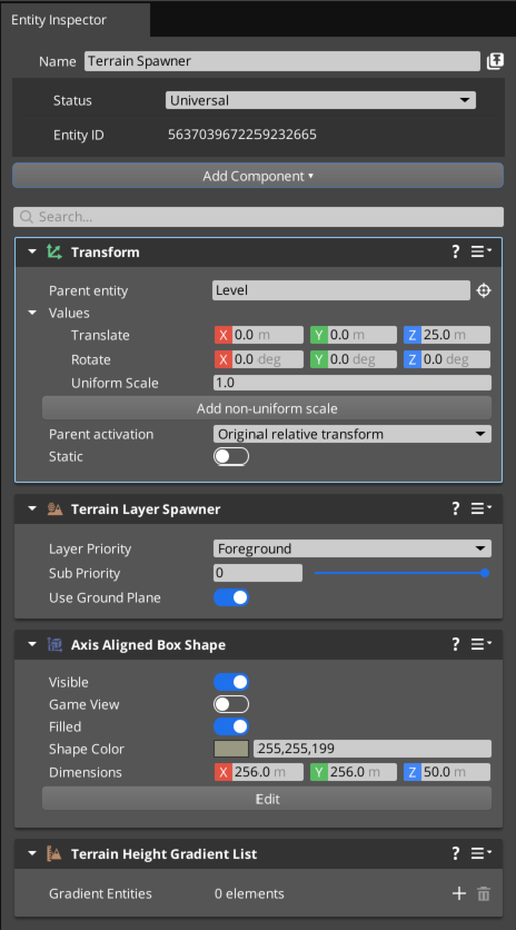
Terrain Spawner.With the entity selected, set each dimension of the Transform component’s Translate values to
0.0 mso that the entity exists at the origin of the world.Add a Terrain Layer Spawner component. This component enables the entity to generate terrain.
The Terrain Layer Spawner component displays a warning about missing a required component. Choose Add Required Component and select Axis Aligned Box Shape from the list. This box shape defines the extents of the generated terrain.
To generate terrain that is the same resolution as the heightmap, in the Axis Aligned Box Shape component, set the value of the Dimensions: X and Y properties to the resolution (in pixels) of the heightmap. The Dimensions: Z property can be used to scale the elevation. Enter a value for the Dimensions: Z property that roughly represents the maximum desired elevation in meters. Our tutorial heightmap image is 256 x 256 pixels and represents a 50 meter change in elevation, so set the dimensions to
(256.0, 256.0, 50.0). If you wish to use a different heightmap, set the dimensions as appropriate for that heightmap’s resolution.
Tip:For the best results, the X and Y dimensions of the Axis Aligned Box Shape should be set to the heightmap pixel size multiplied by the Height Query Resolution. This ensures that there is exactly one heightmap pixel for each world unit used by the terrain system. When the Height Query Resolution is set to 1 meter (the default), the box size in meters should be exactly the same as the heightmap pixel resolution. If the box dimensions are too small, some heightmap pixels won’t get used, which can cause unexpected smooth areas or areas of excessively sharp elevation changes.
- The Axis Aligned Box Shape is centered around the entity’s position, so with the entity at
(0.0, 0.0, 0.0)the box extends from-25.0to25.0on the Z axis. However, by default the minimum terrain elevation is set to0.0. The bottom of the box shape needs to be at least at the minimum terrain elevation value on the world Z axis because any terrain below the minimum elevation will be clipped. In the Terrain Spawner entity, in the Transform component, set the Translate: Z property to a value that is half of the value you used for the Dimensions: Z property in the previous step. For example, if you entered50.0in the previous step, use25.0for the Translate: Z property to move the entity up so that the bottom of the box is at0.0on the world Z axis and the top of the box extends to50.0.
Tip:Once you have set the dimensions of the box shape, you can hide it by disabling the Filled property in the Axis Aligned Box Shape component.
- In Entity Inspector, add a Terrain Height Gradient List component to the Terrain Spawner entity. This component will reference the gradient entity in a later step.
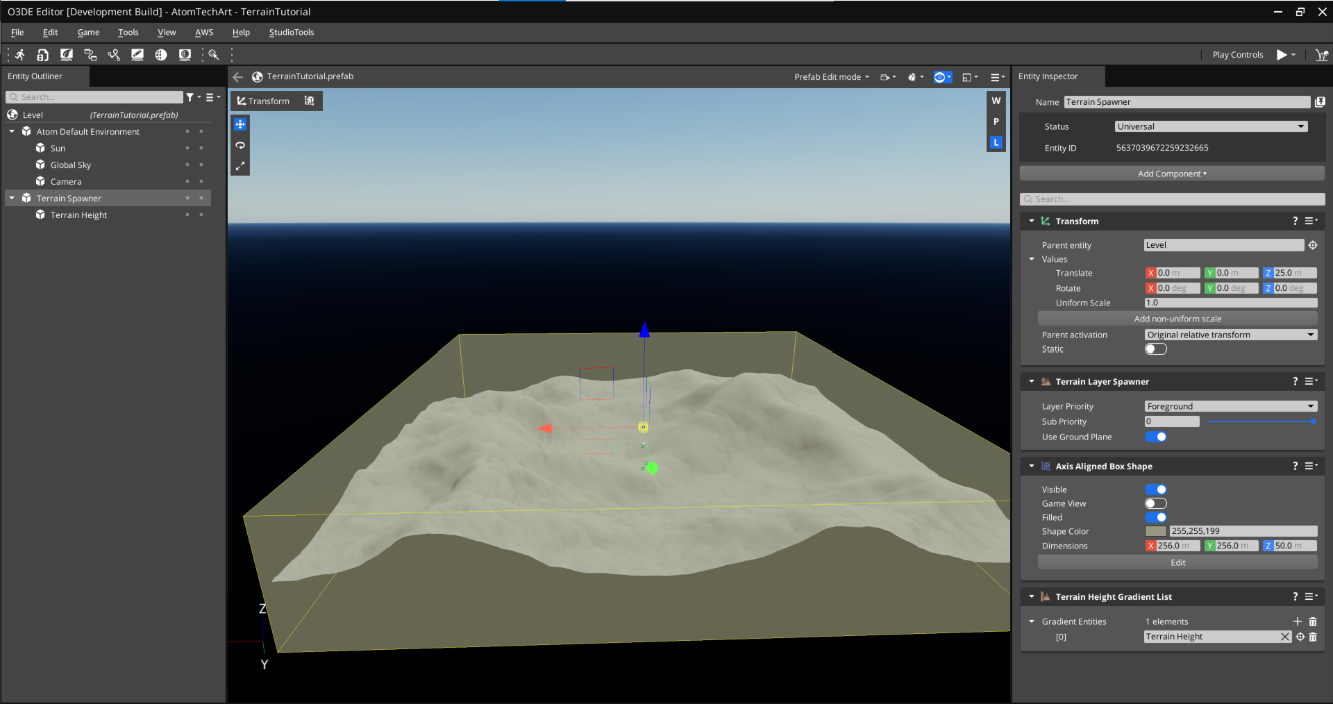
The following image is the complete Terrain Spawner entity:
Create a terrain height gradient entity
With the Terrain Spawner entity selected, create a new child entity (hotkey Ctrl + Alt + N). Name the new entity
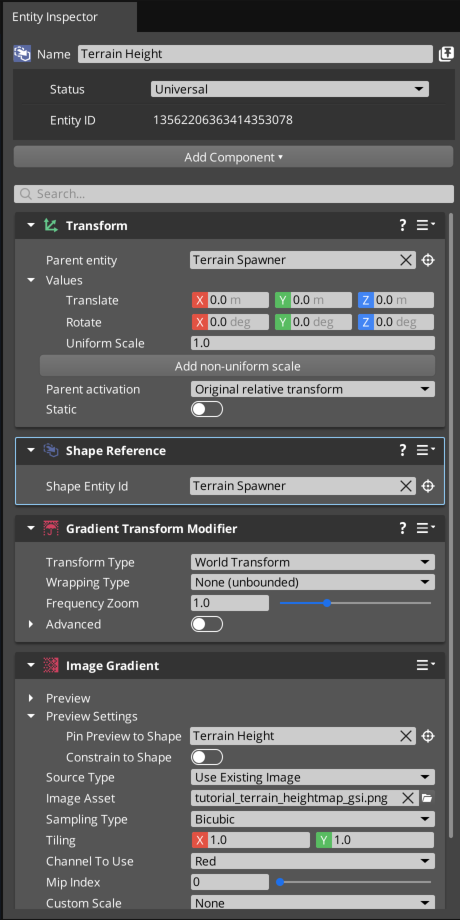
Terrain Height.Add an Image Gradient component to the Terrain Height entity. You’ll use the Image Gradient component to add and configure the heightmap for the terrain.
The Image Gradient component displays a warning about missing a required component. Choose Add Required Component and select Gradient Transform Modifier from the list. The Gradient Transform Modifier component can be used to transform the gradient in world space.
The Gradient Transform Modifier component displays a warning about missing a required component. Choose Add Required Component and select Shape Reference from the list. In a later step, you’ll add a reference to the Axis Aligned Box Shape component in the Terrain Spawner entity to ensure the terrain bounds and the gradient bounds are identical.
Add the heightmap to the Terrain Height entity. In the Image Gradient component, to the right of the Image Asset property, click the
File button and select the
tutorial_terrain_heightmap_gsiheightmap asset that you saved in your tutorial level folder, or optionally any other heightmap image you would like to use.
Tip:Change the Sampling Type property in the Image Gradient component fromPointtoBilinearorBicubicto make the elevation changes smoother in case the heightmap resolution and the dimensions of the Axis Aligned Box Shape component should ever differ.
The Shape Reference component needs to reference the Axis Aligned Box Shape component in the Terrain Spawner entity. In the Shape Reference component, click the
Picker button, then click the Terrain Spawner entity in Entity Outliner to create the reference. The following image shows the final Terrain Height entity:
Select the Terrain Spawner entity. In the Terrain Height Gradient List component, click the
Add button to add a new gradient slot. Click the
Picker button, then click the Terrain Height entity in Entity Outliner to create a reference.
Select the Terrain Height entity. In the Gradient Transform Modifier component, set the Wrapping Type property to
Clamp To Edge. Leaving this property set toUnboundedmight create artifacts at the edges of the terrain.Save the level (hotkey Ctrl + S).
Note:Before continuing to the next section, be sure to learn about terrain setup with Landscape Canvas by selecting the tab at the top of this section.
If you worked through terrain creation with entities in the left tab, you can see how that method might be time consuming and difficult to troubleshoot. Landscape Canvas can greatly simplify the process and provide an easy to understand visual graph for the relationships between the various entities that generate the terrain. Landscape Canvas is particularly useful when you create complex networks of gradients and gradient modifiers to define terrain elevation and surface types.
In this section, you’ll create terrain based on a heightmap with Landscape Canvas.
If there is an existing terrain in your level, delete it.
In O3DE Editor, from the Tools menu, select Landscape Canvas.
In Landscape Canvas, from the File menu, choose New Asset (hotkey Ctrl + N). Notice that a new graph named Entity1 appears in the Landscape Canvas view. In O3DE Editor, a corresponding entity is created that contains a Landscape Canvas component. As you work in Landscape Canvas, additional entities are created and added as children of Entity1. You can rename the entities created by Landscape Canvas.
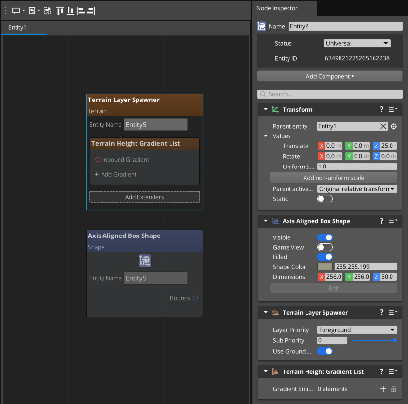
In Landscape Canvas, in the Node Palette, expand the Terrain node list, and drag a Terrain Layer Spawner node into the graph. Notice that in O3DE Editor, a new child entity named Entity2 is created with the necessary components for a terrain spawner. Also notice that the components are displayed in Node Inspector in Landscape Canvas.
In Landscape Canvas, on the Terrain Layer Spawner node, choose Add Extenders and select Terrain Height Gradient List from the list. This adds a Terrain Height Gradient List component to the terrain spawner entity that you’ll use to reference the heightmap later in this tutorial.
In Node Inspector, in the Axis Aligned Box Shape component, set the value of the Dimensions: X and Y properties to the resolution (in pixels) of the heightmap. Enter a value for the Dimensions: Z property that represents the maximum desired elevation change in meters. Our tutorial heightmap image is 256 x 256 pixels and represents a 50 meter change in elevation, so set the dimensions to
(256.0, 256.0, 50.0). If you wish to use a different heightmap, set the dimensions as appropriate for that heightmap’s resolution.In Node Inspector, in the Transform component, set the Translate: Z property to a value that is half of the value you used for the Dimensions: Z property in the previous step. For example, if you entered
50.0in the previous step, use25.0for the Translate: Z property to move the entity up so that the bottom of the box is at 0 on the world Z axis. The following image shows the completed Terrain Layer Spawner node:In Landscape Canvas, in the Node Palette, expand the Gradients node list, and drag an Image node into the graph. Notice that in O3DE Editor, a new child entity named Entity3 is created with the necessary components for an image gradient. Also notice that the components are displayed in Node Inspector in Landscape Canvas.
In the Image node, in the Image Gradient component, to the right of the Image Asset property, click the
File button and select the
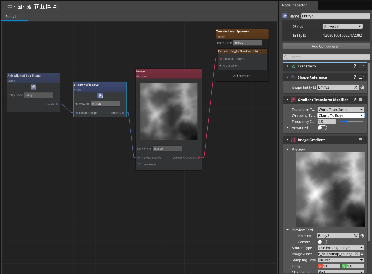
tutorial_terrain_heightmap_gsiheightmap asset that you saved in your tutorial level folder, or optionally any other heightmap image you would like to use.Click the Bounds pin of the Axis Aligned Box Shape node, and drag to the Inbound Shape of the Shape Reference node to connect the nodes and point the Image Gradient to use the same box as the terrain.
Click the Outbound Gradient pin of the Image node, and drag to the Inbound Gradient of the Terrain Layer Spawner node to connect the nodes and generate the terrain. The final graph and the Image node configuration are shown in the following image:
Save the level (hotkey Ctrl + S).
Optionally adjust the height settings
With the entities complete, the Terrain Spawner generates untextured terrain with varying heights similar to the following example:
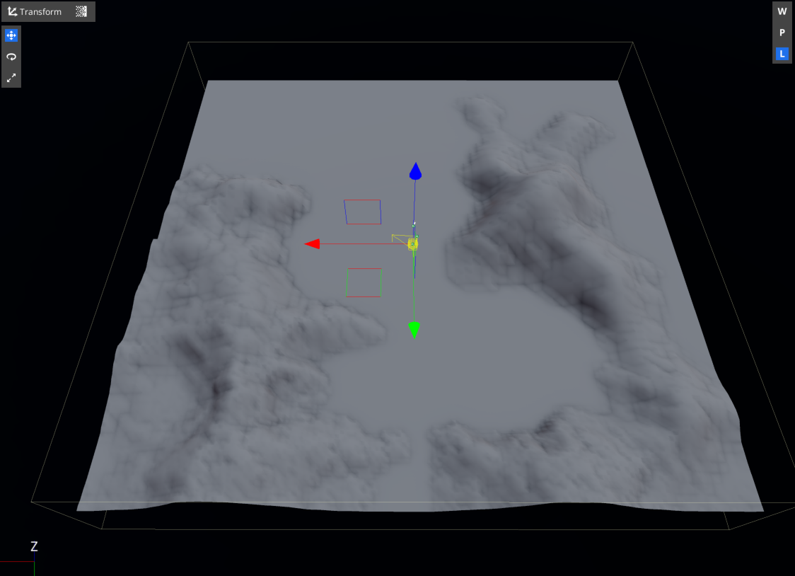
You might, however, have issues where the valleys and peaks in your terrain appear flat due to clipping. The following image shows a terrain that has been placed so that the bottom of its box shape falls below the Min Height specified in the Terrain World level component:
The following properties are closely related and might require special attention if you have issues with your terrain such as clipping:
The Min Height and Max Height properties of the Terrain World level component define the vertical range in the level for terrain generation. This range should be large enough to encompass the vertical extents of the box shape of the Terrain Spawner entity. If the box shape extends below the Min Height value or above the Max Height value, the terrain valleys or peaks are clipped.
The Dimensions property of the Axis Aligned Box Shape component specifies the terrain area. The Dimensions: Z property, in particular, specifies the height of the terrain. Its value should not exceed the range defined in the Terrain World level component by the Min Height and Max Height properties.
The Translate property of the Transform component of the Terrain Spawner entity places the terrain entity in the level. The translate position of the Terrain Spawner entity is at the center of the box shape that defines the terrain area. This means that if the box shape is a 512 unit cube, and the Translate property is
0.0on each axis, then the terrain extends 256 units in each direction from the origin of the level. Be careful to ensure that the Translate: Z value places the box shape within the range defined by the Min Height and Max Height properties of the Terrain World level component.
Optionally adjust the terrain mesh rendering settings
If you are using the tutorial assets, the default terrain mesh rendering settings are sufficient. However, if you chose to use a different heightmap and terrain spawner box size than what’s listed in the tutorial, and if the box size is larger than the default terrain rendering distance of 4096 meters or the default camera view distance of 1024 meters, you will need to adjust the rendering distances to make the entire terrain visible.
In the Terrain World Renderer level component, set the Mesh render distance to a value that is greater than the terrain spawner box size so that the entire terrain will be visible.
If the box size is larger than 256 x 256, do the following:
i. Set the First LOD distance property to
256. This sets the terrain’s highest level of detail (LOD) display to a distance of 256 meters from the camera.ii. Set the CLOD Distance property to
32. This sets the blend distance between LODs to 32 meters. Larger values make the LOD transitions smoother, but the value should be less than 1/4 of the First LOD distance value to ensure that there is enough distance to blend each LOD.In the Camera entity, in the Camera component, set the Far clip distance property to a value that is greater than the box size.
In the Camera entity, in the Camera component, choose Be this camera to view the level through the camera entity.
In the Edit menu, Editor Settings, Global Preferences…, in the Camera preferences set the Camera Movement Speed to an appropriate value for the size of the terrain.
100.0is a good reference point for large terrains.
These suggestions are meant to help you view the entire terrain while you build it in O3DE Editor. In Launcher applications, these settings should be tuned for an appropriate balance of performance and quality.

