IN THIS ARTICLE
Working with the 3D Viewport
In Open 3D Engine (O3DE), you can interact directly with entities using the 3D Viewport. The 3D Viewport provides several features to complete common tasks such as editing the position, rotation, and scale of entities, hierarchies of entities, and their components. UI widgets, Manipulators, Hotkeys, and visual feedback mechanisms simplify the process of editing and arranging entities. With Reference spaces, you can quickly select if entities are transformed in world space, local space, in relation to a parent entity, or custom spaces.
Viewport UI widgets
Transform mode widget
You can select one of the three transform modes with the transform mode widget, translate, rotate, or scale. Each transform mode displays a unique Manipulator on the entity in the 3D Viewport that you can adjust with the mouse. Select a transform mode by clicking the widget with the mouse or using a keyboard hotkey listed in the following table. You can quickly switch between translate and rotate modes by pressing Ctrl + Mousewheel Up/Down.

| Mode | Keyboard Hotkey | Description |
|---|---|---|
| Translate | 1 | Moves an entity along an axis, plane, or surface. |
| Rotate | 2 | Rotates an entity on one of three axes or in relation to the camera. |
| Scale | 3 | Uniformly scales an entity’s size. |
Reference space widget
Reference spaces set the alignment of manipulator axes. By default, entities will translate and rotate in local space, which is determined by an entity’s Rotate and Translate values in the
Transform component. World space is constant at all times for all entities. World space is always centered at the Translate coordinates of (0, 0, 0) without any rotation. If an entity is the child of another entity, parent space will reference the Rotate and Translate values of the parent entity’s Transform component. You can left-click on an icon in the widget to lock a reference space selection; left-click the icon again to return the reference space to the default, local space.

| Mode | Keyboard Hotkey | Description |
|---|---|---|
| World space | Hold Shift | Manipulators align with the unchanging world space that is common to all entities in a level. |
| Parent space | If an entity has a parent, manipulators align with the parent’s rotation. | |
| Local space | Manipulators align with the rotation of the entity that is selected. |
Component mode switcher

Every entity in the 3D viewport has a Transform component. Other components that you can add to entities have properties that are easily edited in the 3D viewport using the component’s edit mode. You can left-click the icon of an editable component to enter that component’s edit mode. The Transform component’s edit mode is selected by default.
The following table lists some of the components with an edit mode and describes the tasks you can complete while it is selected in the component mode switcher. Refer to a component’s page in the Component Reference for a description of actions you can take while in edit mode.
| Component | Edit Mode Tasks |
|---|---|
| Shape | Edit the dimensions of the various shape components. |
| White Box Tool | Design models with the White Box Tool. |
| Spline | Add, remove, and position spline control points. |
| Non-uniform Scale | Edit the scaling of an entity on the X, Y, and Z-axis separately. |
| PhysX Collider | Edit the dimensions of a collider. |
| PhysX Ball Joint | Edit the position and limitations of a joint. |
Manipulators
With manipulators, you can edit an entity’s Transform component properties directly in the 3D Viewport instead of in the Entity Inspector. When you select an entity, only the current transform mode’s manipulator displays. The orientation of the manipulator matches the reference space selection.
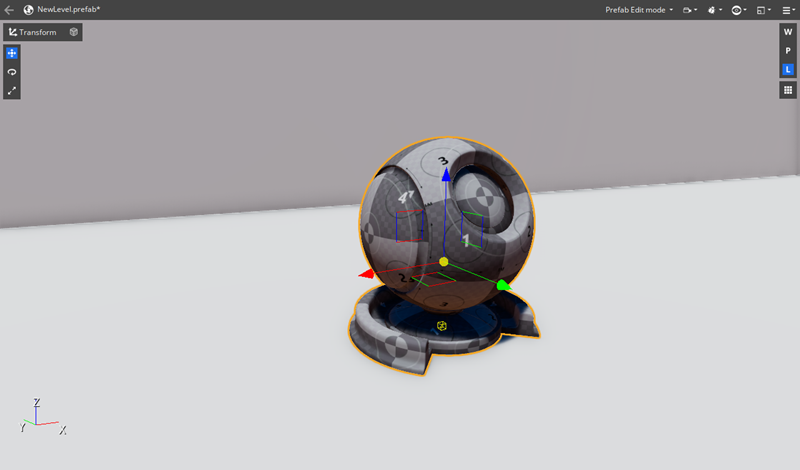
Translation manipulator
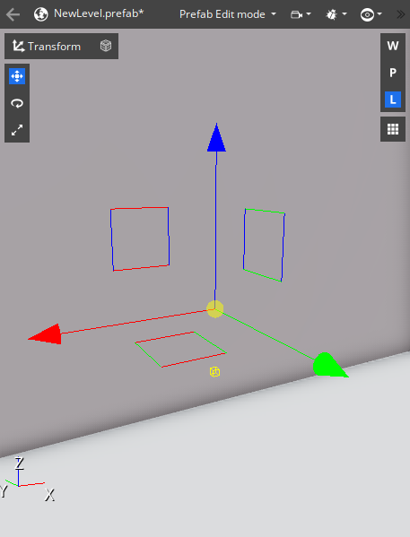
The translation manipulator is composed of three different types of manipulators. The red, green, and blue arrows are linear manipulators, they correspond to the X-axis, Y-axis, and Z-axis, respectively. You can left-click and drag a linear manipulator to move an entity along a single axis at a time. Manipulators turn yellow when you hover over them.
Use Planar manipulators, represented by squares, to move an entity along two axes while restricting movement on the unselected axis.
The yellow sphere at the center of the translation manipulator is the surface manipulator. You can move an entity along the surface of other meshes that are visible in the 3D Viewport. If there are no surfaces that the entity would intersect with, the entity will move a fixed distance in front of the camera.
The translation manipulators display a red, blue, and green ghost axis that indicates the original position of the entity while a manipulator is in use.
Rotation manipulator
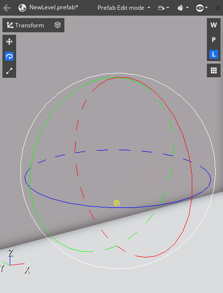
The rotation manipulator is composed of two types of manipulators. A set of red, green, and blue circles are angular manipulators that rotate the entity on the X-axis, Y-axis, and Z-axis, respectively. The larger white circle is the camera space manipulator, which rotates the entity on the Editor camera’s forward axis. Left-click and drag a manipulator to rotate the entity on an axis.
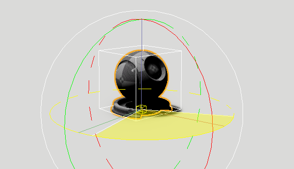
The rotation manipulators display a yellow sector that indicates the original orientation of the entity while a manipulator is in use.
Scale manipulator
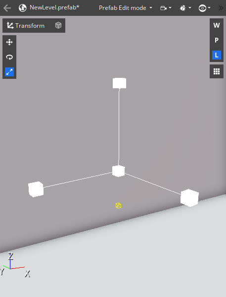
The scale manipulator is represented by a set of white cubes on a 3D axis. You can left-click and drag away from the manipulator’s center to increase the uniform-scale of an entity.
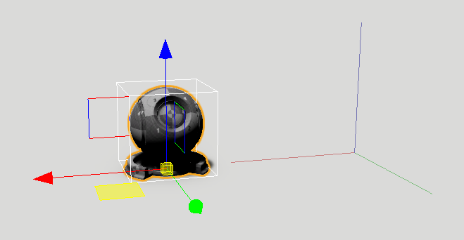
Pivots
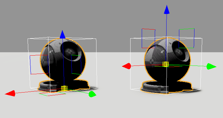
Entities with a three-dimensional shape may have more than one pivot point. In the viewport, the pivot point is indicated by a small yellow cube. The default pivot point is located at the local origin of the entity, often this is set when the 3D object is modelled in a DCC tool and imported into O3DE. The second pivot point of an entity is located at the geometric center of the object’s volume. You can switch between the two pivot points by pressing P on the keyboard.
An entity’s pivot point determines the fixed point that an entity rotates around and scales from.
Hotkeys
Refer to the following table for a summary of keyboard hotkeys for the 3D Viewport.
| Default Hotkey | Action | Note |
|---|---|---|
| 1 | Displays the translation manipulator. | |
| 2 | Displays the rotation manipulator. | |
| 3 | Displays the scale manipulator. | |
| Ctrl + Mousewheel Up/Down | Switches between the translation and rotation mode manipulators. | |
| R | Resets the entity’s transform. | Only resets the transform values for the current transform mode. |
| Ctrl + Drag Translation manipulator | Sets all manipulators to a custom translation. | Sets a custom pivot point for rotation and scaling. |
| Ctrl + Drag Rotation manipulator | Sets all manipulators to a custom rotation. | Sets a custom rotation for the axes of translations. |
| Ctrl + Drag Scale manipulator | Sets the size of all manipulators. | |
| Ctrl + R | Resets the current manipulator. | |
| P | Toggles the pivot of the selected entity. |