IN THIS ARTICLE
Synchronizing Animation Graphs: Example
You can use synchronized animation graphs to synchronize animation between actors. For example, the animation of one actor might trigger an animation in another actor. An animation graph can be the primary graph and have multiple secondary graphs. Likewise, an animation graph can be both a secondary graph of one graph and a primary graph for another graph.
This topic describes the following main steps for synchronizing two animation graphs:
Add the required components to the entities to be synchronized, including the Anim Graph component.
Use Animation Editor to create a motion set and one or more animation graphs.
Add a parameter to the secondary graph to receive the change event from the primary graph.
Add a parameter to the primary graph.
Add a servant parameter action to the primary graph to send change events to the secondary graph.
Synchronize the graphs by using O3DE’s Event Bus (EBus) system and Lua script.
This topic illustrates this graph synchronization with an example that has two actors, a robot actor (“Jack”) and a gun actor. When the player activates the sync mode and uses the keyboard to fire, the robot makes a firing motion and the gun fires. When the player deactivates the sync mode, the robot makes a firing motion, but the gun does not fire.
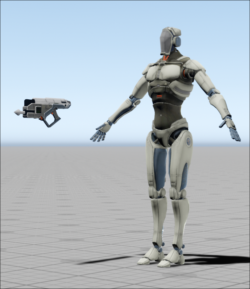
The robot has a syncFeature_Jack animation graph and the gun uses a syncFeature_Gun graph. The robot graph is the primary graph and the gun graph is the secondary graph.
When the sync mode is on, the gun fires in sync with the robot. When the robot fires, the state of the primary graph’s shoot parameter is received by secondary graph’s gunTrigger parameter. The secondary graph, which is attached to the gun, receives the parameter change event and fires the gun.
1. Add Required Components
The first step is to add the required components to the entities that you want to synchronize. The robot and gun components that are used by the entities in the example are described in the following sections.
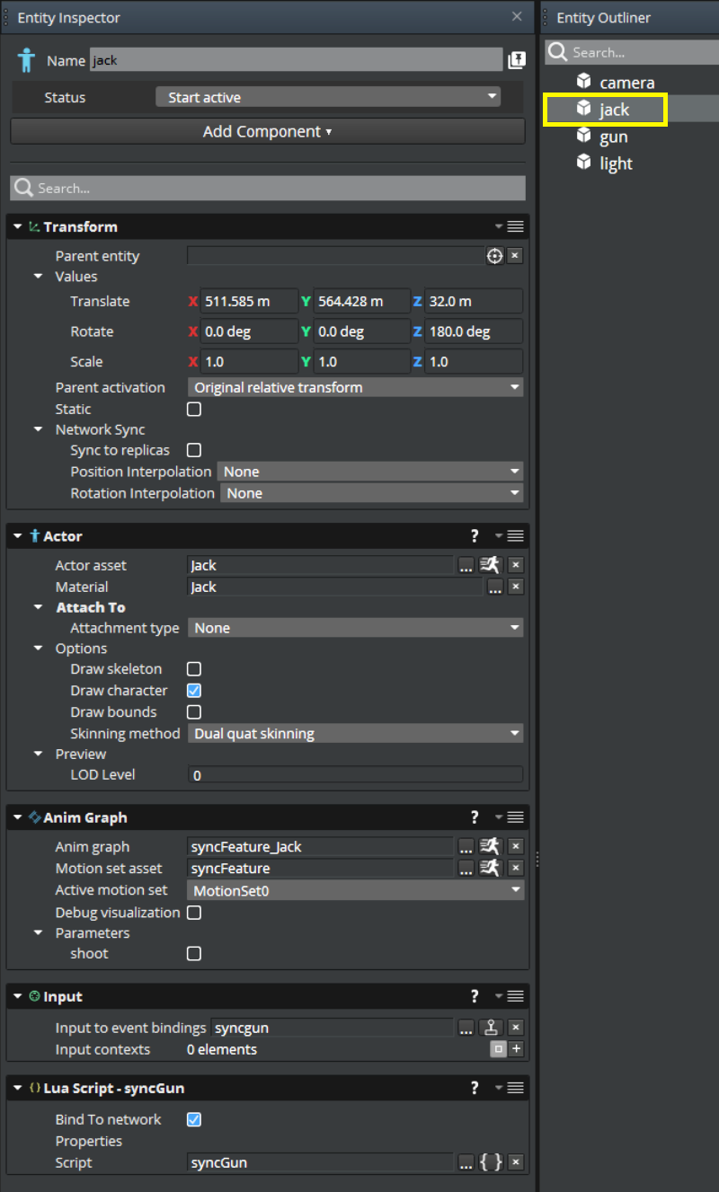
Robot Entity Components
The robot entity uses the following components:
- Transform
- Actor
- Anim Graph
- Input
- Lua Script
The following image shows the configuration of the components for the robot entity in the Entity Inspector.
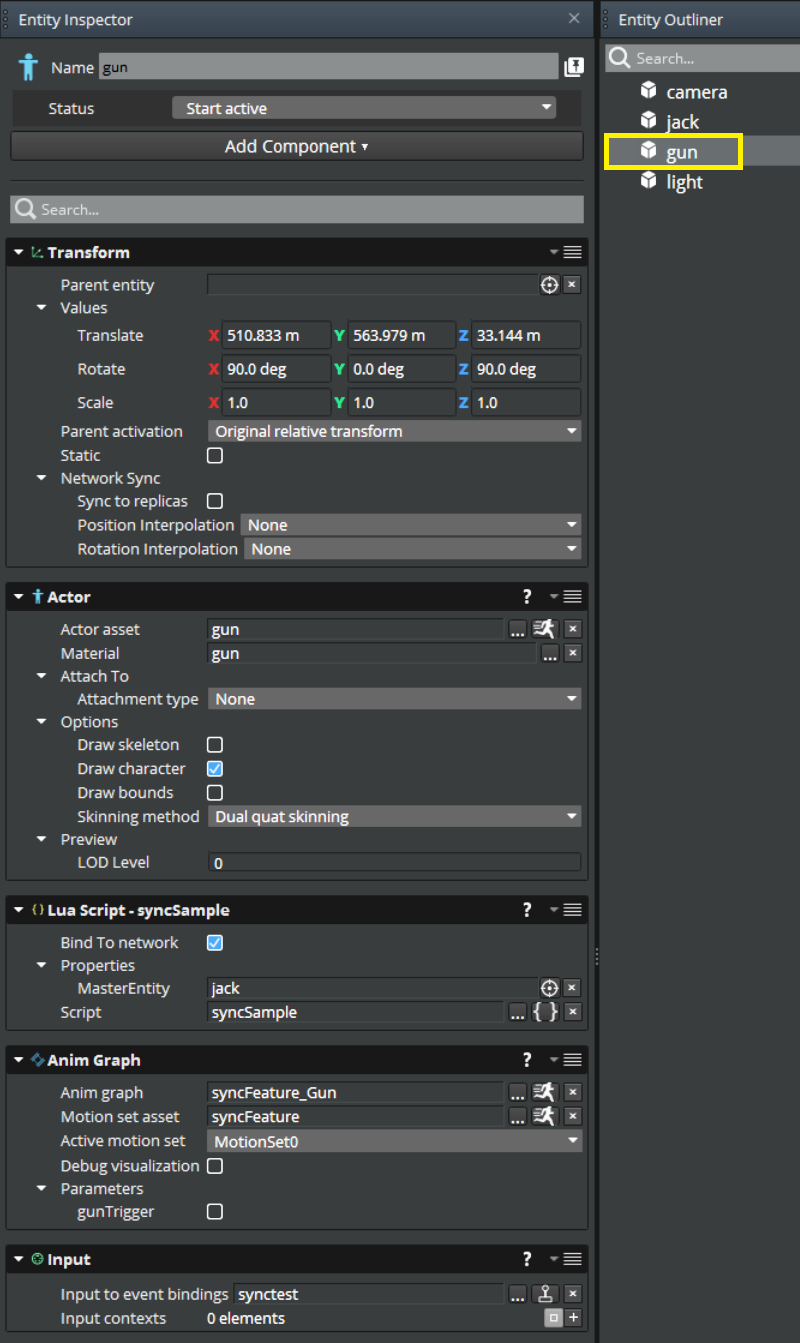
Gun Entity Components
The gun entity uses the following components:
- Transform
- Actor
- Lua Script
- Anim Graph
- Input
The following image shows the configuration of the components for the gun entity in the Entity Inspector.
2. Create a Motion Set and Animation Graphs
After you set up your entities and components, create a motion set and two animation graphs. The motion set contains the motions that your graphs use, and the secondary and primary animation graphs animate and synchronize the entities.
To create a motion set and two animation graphs
- Create a motion set. For information about creating a motion set, see
Getting Started with the Animation Editor. This example’s MotionSet0 contains the motions
gunshootanimation,jack_shoot, andjack_idle.

Create a secondary animation graph. For information about creating a secondary animation graph, see Getting Started with the Animation Editor. The secondary graph controls one or more entities whose actions are determined by the primary graph.
This example’s
syncFeature_Gunsecondary graph has a BindPose0 node and a Motion0 node. The Motion0 node contains thegunshootanimationmotion.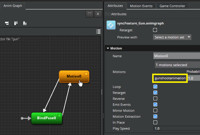
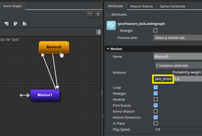
Create a primary graph. The primary graph sends control events to the secondary graph.
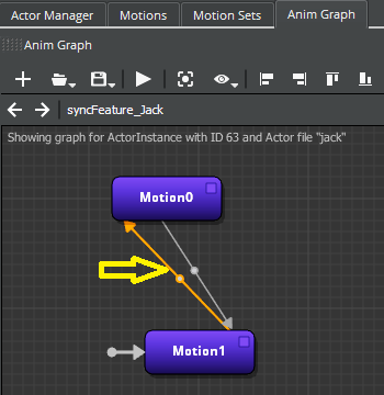
This example’s
syncFeature_Jackprimary animation graph has a Motion1 node and a Motion0 node. The Motion1 node contains thejack_idlemotion and the Motion0 node contains thejack_shootmotion.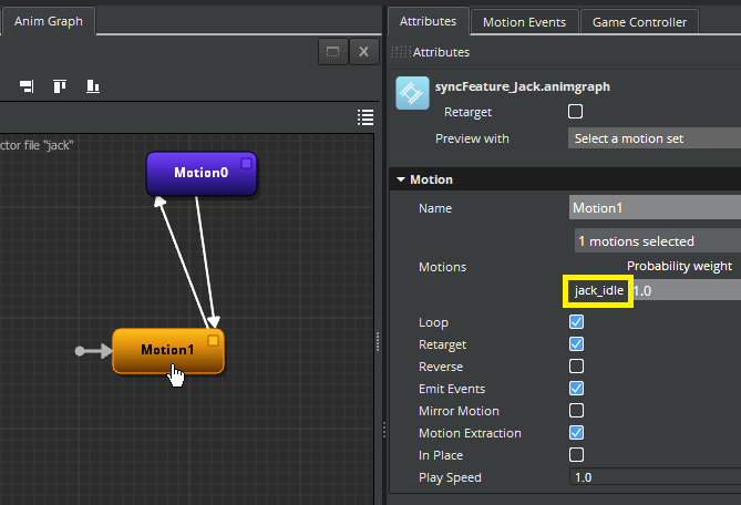
3. Add a Parameter to the Secondary Graph
You are now ready to add a parameter to the secondary graph that receives the parameter change event from the primary graph. After you add the parameter, add parameter conditions that specify when the animation transitions from one motion to another.
To add a parameter to the secondary graph to receive the change event from the primary graph
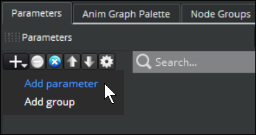
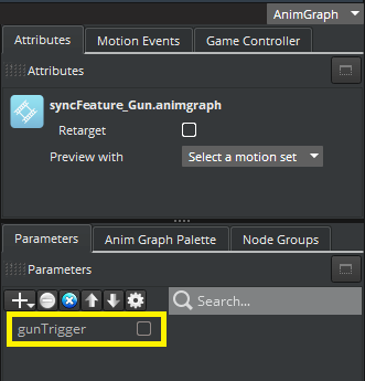
- On the Parameters tab for the secondary animation graph, click the plus (+) icon, and choose Add parameter.
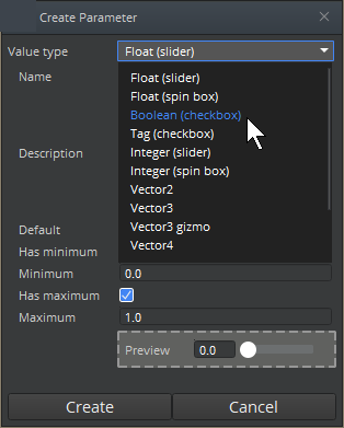
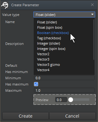
- In the Create Parameter dialog box, for Value type, choose the data type that you want to use for the parameter. This example uses the Boolean (checkbox) value type because the gun trigger is either on or off.
- For Name, enter a name for the parameter. This example uses
gunTrigger.
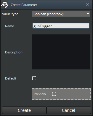
- Click Create. The Parameters list shows the parameter that you created.
Add Parameter Conditions to the Secondary Graph
In this section, add parameter conditions on the transition lines that specify when the animation changes. In the example, the conditions indicate whether the gun trigger has been pressed.
To add parameter conditions to the secondary graph
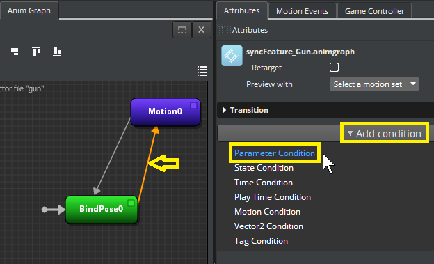
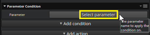
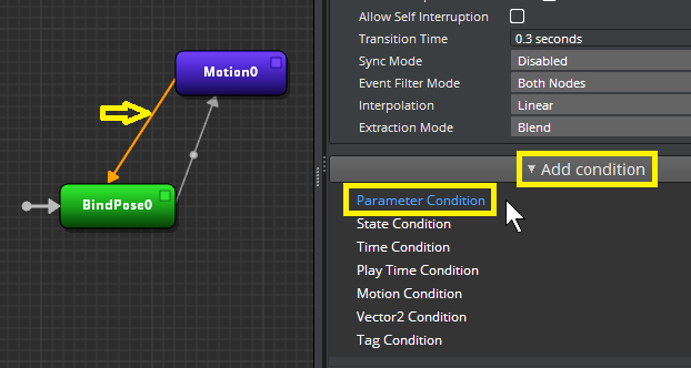
- Click the transition line from the BindPose0 node to the Motion0 node. Then, in the Attributes pane, click Add condition, and choose Parameter Condition.
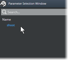
- Click Select parameter.
- In the Parameter Selection Window, choose the parameter that you just created, and click OK.
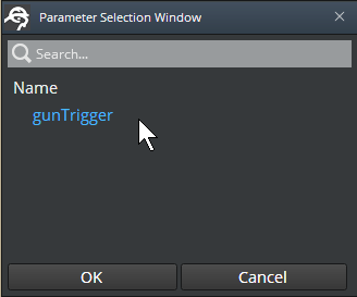
In the Attributes pane, a Parameter Condition section shows the parameter that you added. On the transition line, a small round node indicates that the line has a parameter condition.
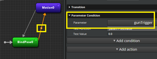
- For Test Function, use the default value of param > testValue. In this example, this means that if the trigger receives a value greater than 0, the gun fires.
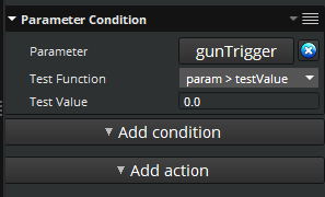
For Test Value, keep the default value of 0.0.
Click the transition line from the Motion0 node to the BindPose0 node. Then, in the Attributes pane, click Add condition, and choose Parameter Condition.
Click Select parameter.
In the Parameter Selection Window, choose the parameter that you are using. The example uses the
gunTriggerparameter.For Test Function, use the default value of param == testValue. In this example, this means that if the trigger value is equal to zero, the motion transitions back to idle, and the gun no longer fires.
For Test Value, keep the default value of 0.0.
Now the secondary animation graph is ready to receive signals from the primary graph.
4. Add a Parameter and Parameter Conditions to the Primary Graph
You add a parameter and parameter conditions to the primary graph just as you did with the secondary graph. However, you also add secondary (“servant”) parameter actions to the primary graph. The actions signal the secondary graph to mimic the animations of the primary graph.
To add a parameter to the primary graph
- On the Parameters tab, click the plus (+) icon, and choose Add parameter.

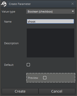
- In the Create Parameter dialog box, for Value type, choose the data type that you want to use for the parameter. This example uses the Boolean (checkbox) value type because the gun trigger is either on or off.
- For Name, enter a name for the parameter. This example uses
shoot.
- Click Create.
Add Parameter Conditions to the Primary Graph
Now you add parameter conditions on the transition lines in the primary graph as you did on the secondary graph.
To add parameter conditions to the primary graph
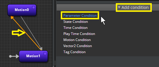
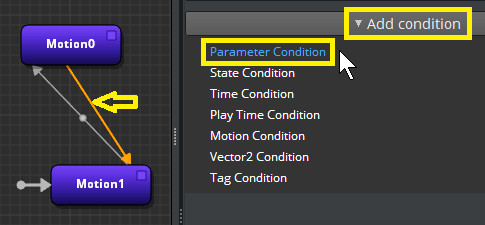
- Click the transition line from the Motion1 node to the Motion0 node. Then, in the Attributes pane, click Add condition, and choose Parameter Condition.
Click Select parameter.
In the Parameter Selection Window, choose the parameter that you just created. This example uses
shoot.
For Test Function, use the default value of param > testValue.
For Test Value, use the default value of 0.0.
Click the transition line from the Motion0 node to the Motion1 node. Then, in the Attributes pane, click Add condition, and choose Parameter Condition.
Click Select parameter.
In the Parameter Selection Window, choose the parameter that you are using. The example uses
shoot.For Test Function, use the default value of param == testValue.
For Test Value, use the default value of 0.0.
5. Add Servant Parameter Actions to the Primary Graph
Now you are ready to add secondary (“servant”) parameter actions to the primary graph. A script uses these actions to synchronize the two graphs.
To add a servant parameter action to the primary graph
- In Animation Editor, click to select the first transition line again. This example selects the line from the
jack_idlenode Motion1 to thejack_shootnode Motion0.
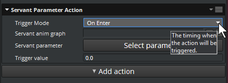
- In the Attributes pane for the primary graph, click Add action, Servant Parameter Action.
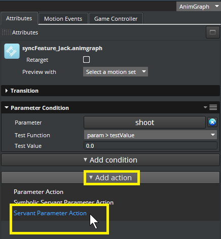
- For Servant Parameter Action, in the Trigger Mode box, keep the default On Enter. On Enter specifies that the action is triggered when the state or transition is entered.
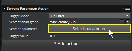
In the Servant anim graph box, click Browse (…) and choose the secondary animation graph that has the parameter that you want to use. This example chooses a secondary animation graph called syncFeature_Gun.
Click Select parameter to choose a parameter from the secondary animation graph that you just chose. This example chooses the gunTrigger parameter.
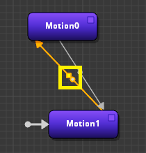
On the transition line, a small square node indicates that the transition line has a parameter action. The small round node next to it represents the parameter condition that you added earlier.
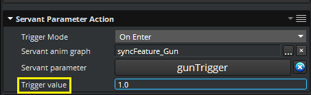
- For Trigger value, specify the value to emit when the action is triggered. Because Trigger value is treated as a single float, you can use it for float, Boolean, and integer parameters. This example specifies
1.0, which is the value when the gun fires.
Click the line from Motion0 to Motion1 and repeat the steps to add a servant parameter action to the remaining transition line.
In the Trigger value box, specify a different value. The example specifies a trigger value of
0.0, which is the value when the gun is idle.
Now that the animation graphs are ready, you can perform the next steps: gathering user input and writing Lua scripts to synchronize the graphs.
6. Synchronize the Primary and Secondary Graphs
Synchronizing the primary and secondary graphs involves the following steps:
Getting keyboard input from the player.
Placing a Lua script component and Lua script on the secondary entity.
Placing a Lua script component and Lua script on the primary entity.
The Lua scripts synchonize the two graphs by handling animation graph events in O3DE’s Event Bus (EBus) system.
Getting Input from the Player
In the example, the synchronization state of the primary and secondary graphs and the firing of the gun are controlled by the following keyboard inputs, or keystrokes, from the user. The Event Value Multiplier is the actual value sent to the input system and to Lua script.
| Keystroke | Description | Event Value Multiplier |
|---|---|---|
| 1 | Turns on sync mode. | 1 |
| 2 | Turns off sync mode (off by default). | -1 |
| S | Fires the gun. | 1 |
| D | Stops the gun from firing. | -1 |
To gather these inputs, the example adds Input components to the robot entity and to the gun entity.
To use the Input component, you must enable the
Starting Point Input Gem for your project. The Starting Point Input Gem interprets hardware input and converts it into input events such as pressed, released, and held.
Each Input component references an .inputbindings file. An .inputbindings file binds a set of inputs to an event. These inputs can come from sources such as a mouse, keyboard, or game controller. To create an input bindings file, you can use the Input Bindings Editor in O3DE Editor. For more information, refer to
Using Player Input in Open 3D Engine.
Getting Keyboard Input to Control Graph Synchronization
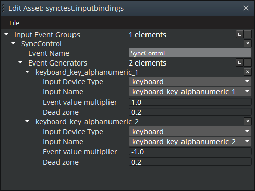
In the example, the gun entity has an Input component. The Input component uses a synctest.inputbindings asset to bind keyboard inputs 1 and 2 to the SyncControl event. The SyncControl event controls the sync mode, which determines whether or not the gun fires when the robot fires.
The following image shows the corresponding input bindings in the Input Bindings Editor.
Getting Keyboard Input to Control Shooting
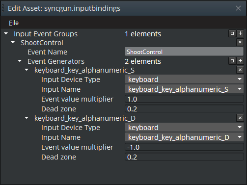
The Input component on the robot uses a syncgun.inputbindings asset to bind keyboard inputs S and D to the ShootControl event. The ShootControl event controls the firing of the gun.
The following image shows the corresponding input bindings in the Input Bindings Editor.
Using a Script on the Secondary Graph to Toggle Synchronization
The example uses Lua Script components on both the primary (robot) and secondary (gun) entities. The script on the primary entity controls the firing of the gun. The script on the secondary entity controls the sync mode. To add a Lua script to an entity, add a Lua Script component to the entity and then attach the script to the component.
The Lua script on the gun entity receives the input from the keyboard to toggle the sync mode. To synchronize the secondary graph to the primary graph, the script uses the SyncAnimGraph EBus event. In the following example, the self.entityId parameter refers to the secondary entity (the gun). The self.Properties.PrimaryEntity parameter refers to the robot.
AnimGraphComponentRequestBus.Event.SyncAnimGraph(self.entityId,self.Properties.PrimaryEntity);
To desynchronize the secondary graph from the primary graph, the same script uses the DesyncAnimGraph EBus event.
AnimGraphComponentRequestBus.Event.DesyncAnimGraph(self.entityId,self.Properties.PrimaryEntity);
The full script shows how the SyncAnimGraph and DesyncAnimGraph methods handle the SyncControl input event.
-- syncSample.lua
local syncSample =
{
	Properties =
    {
		PrimaryEntity = { default = EntityId() }
	},
}

function syncSample:OnActivate()
    self.SyncControlInputBusId = InputEventNotificationId("SyncControl");
    self.SyncControlInputBus = InputEventNotificationBus.Connect(self, self.SyncControlInputBusId);
    self.ShootControlInputBusId = InputEventNotificationId("ShootControl");
    self.ShootControlInputBus = InputEventNotificationBus.Connect(self, self.ShootControlInputBusId);
	self.SyncControl = false;
	self.Shooting = false;
end

function syncSample:HandleSyncControl(floatValue)
	if (floatValue > 0 and self.SyncControl == false ) then
		AnimGraphComponentRequestBus.Event.SyncAnimGraph(self.entityId, self.Properties.PrimaryEntity);
		self.SyncControl = true;
	elseif(floatValue < 0 and self.SyncControl == true ) then
		AnimGraphComponentRequestBus.Event.DesyncAnimGraph(self.entityId, self.Properties.PrimaryEntity);
		self.SyncControl = false;
	end
end

function syncSample:HandleInput(floatValue)
	if (InputEventNotificationBus.GetCurrentBusId() == self.SyncControlInputBusId) then
		self:HandleSyncControl(floatValue);
	end
end

function syncSample:OnPressed(floatValue)
	self:HandleInput(floatValue);
end

function syncSample:OnHeld(floatValue)
    self:HandleInput(floatValue);
end

return syncSample;
Using Script on the Primary Graph to Control Shooting
The example Lua script on the primary entity (the robot) receives the keyboard input that toggles the firing of the gun. The robot entity’s animation graph’s shoot parameter uses the Boolean (checkbox) type. When the gun fires, the shoot parameter is true. Because shoot is a named Boolean parameter, the Lua script on the primary entity uses the SetNamedParameterBool function on the AnimGraphComponentBus.
The full script shows how the SetNamedParameterBool function is used to toggle the shooting status.
-- syncGun.lua
local syncGun =
{
}

function syncGun:OnActivate()
    self.ShootControlInputBusId = InputEventNotificationId("ShootControl");
    self.ShootControlInputBus = InputEventNotificationBus.Connect(self, self.ShootControlInputBusId);
	self.Shooting = false;
end

function syncGun:HandleShootControl(floatValue)
	if (floatValue > 0 and self.Shooting == false ) then
		AnimGraphComponentRequestBus.Event.SetNamedParameterBool(self.entityId, "shoot", true);
		self.Shooting = true;
	elseif(floatValue < 0 and self.Shooting == true ) then
		AnimGraphComponentRequestBus.Event.SetNamedParameterBool(self.entityId, "shoot", false);
		self.Shooting = false;
	end
end

function syncGun:HandleInput(floatValue)
	if (InputEventNotificationBus.GetCurrentBusId() == self.ShootControlInputBusId) then
		self:HandleShootControl(floatValue);
	end
end

function syncGun:OnPressed(floatValue)
	self:HandleInput(floatValue);
end

function syncGun:OnHeld(floatValue)
    self:HandleInput(floatValue);
end

return syncGun;
The Example in Action
The following animated image shows the finished example in action when the sync mode is turned off. The robot fires, but the gun does not.
The following animated image shows the example when the sync mode is turned on. The gun fires when the robot fires.